This chapter covers the CDOT Workspace Drafting Standards which consist of Cell Libraries, Seed Files, Specialty Group DGN Library definition files (Level Libraries or DGNLIB’s), Text and Line Style Resource files, and other pertinent CADD information for creation of project plan sets. These standards establish consistent plan set appearance, format, accuracy, and quality.
CDOT Workspace Drafting Standards have been developed and approved by the Statewide Standards & Configuration (S&C) committee along with input from discipline-specific specialty group task force teams. Users who can not find what they need to complete their work, are encouraged to email comments and suggestions for changes or improvements to the CDOT CADD Manager. Requests will be reviewed and incorporated into future configuration releases upon approval.
The following table shows the required file types.
|
File Type |
File Extension |
File Description |
|
Design Files |
DGN |
Native V8 required |
|
Cell Libraries |
CEL |
V8 Cell Libraries required Cells stored as models |
|
Level Files |
DGNLIB |
V8 Level library definition file |
The libraries are automatically loaded through the use of configuration variable cell library lists (MS_CELLLIST) and available from the Cell Library dialog box within MicroStation. When the user opens a design (.dgn) file in MicroStation, all of the 16 cell libraries will be available for attachment from the Cell library dialog boxes’ File dropdown menu. The Cell Library dialog box contains a location for selecting the Display All Cells in Path. If this toggle is chosen, all cells within the workspace are available for use within the cell list. By default this toggle is not selected.
There are two types of cells available within the CDOT workspace: Graphic cells and Point cells. The major differences include Graphic cells maintaining the symbology they were created with when placed and Point cells taking on the active symbology when placed. The one exception is when Graphic cells are created on the default level. In this case the cell will adopt the active symbology similar to a point cell. Another difference is cell rotation. Graphic cells will remain rotated as placed while Point cells are "view independent". View independent applies to both cells and text and means that if a view is rotated, a plan sheet for example, the cell or text will remain oriented to the view, not as rotated when placed. Graphic cells have become the main choice at CDOT and are utilized wherever possible and point cells have been removed in all but a few cases.
Cells have been created to be placed relative to the plot scale, or the active scale which should be equivalent to the Model Properties>Annotation Scale setting. Cells can be placed in either the Model file or the Sheet file, depending on what type of drawing is being produced. Most cells have been drawn at a 1:1 scale, based on the CDOT Seed file resolution, but there are some exceptions. The scaling exceptions are those cells discussed below. The insertion point of each cell is the coordinate 0,0,0 in each model. When cells are placed into a Model File, the individual Specialty Group lead is responsible for providing the base mapping. If a different scaled model is desired, the group lead should be contacted for the desired scale. The varying scaled base mapping should reside in the Specialty Group folder structure and referenced to the project plan set sheet files.
The Hydraulic (Hydraulics.cel) library contains many true size cells that have been drawn true size and must be placed at an active scale factor of 1 to be true scale. These cells include Plan and Elevation Inlet cells and Plan and Elevation End Sections cells. The Traffic (TRAF_General.cel) library also contains many striping pavement markings that have been drawn true size and must be placed at an active scale factor of 1 to be true scale.
Seed files are the basis for all CDOT MicroStation Design files. Seed files are templates in which parameters have been set for the needs of CDOT. The seed file defines the working units, global origin of the coordinate system, resolution, and 2D vs. 3D definition. A 2D and 3D seed file is available in the CDOT workspace. These seed files should always be used when creating any new design file. A 4-Sig-Fig-Seed.dgn seed file is also available for calling out to the accuracy of four decimal places.
The Project Creation Utility tool, which is used at the beginning of each project, will copy several Project Template files into the appropriate discipline directory structure. These files can also be used for creating new files, as the files are replicated from the appropriate discipline seed file.
CDOT Seed Files
|
Seed File Name |
Description |
|
2D-Seed.dgn |
Standard 2D template for all 2D Seed files |
|
3D-Seed.dgn |
Standard 3D template for all 3D Seed files |
|
4-Sig-Fig-Seed.dgn |
Standard template for call out accuracy of four decimal places |
Working units are controls that are used to set “real world” units of measurement for design models. MicroStation recognizes Metric and Imperial units. CDOT has designated that all design projects be completed in imperial units. Therefore the CDOT Seed files will contain only Imperial Units. The CDOT seed files working units are based on U.S. Survey Feet for Master Unit of measurement and U.S. Survey Inches for Subunit of measurement. CDOT uses the Colorado Coordinate System of 1983 on all roadway design projects; seed files have been set up to accommodate this coordinate system. The CDOT workspace contains a custom unit definition file called units.def which defines these units of measurement.

Seed File Coordinate Readout
The CDOT design resolution for all seed files has been set to 12000 units per Survey Foot. The resolution setting should not be changed. This setting affects the size of all graphical elements within a design Model and, if changed, will incorrectly scale all existing elements.
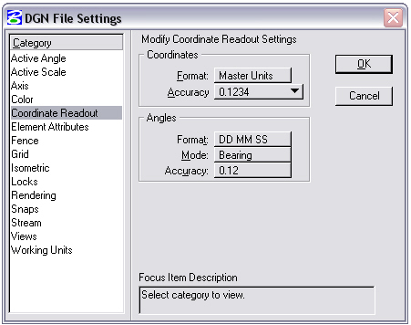
Coordinate Readouts determine the number of decimal places shown and format for the overall readout displayed in the MicroStation Status Bar or AccuDraw window. Readouts specify two settings: Coordinates and Angles.
The Coordinates set the format and decimal readout of the design file, based on the Units specified (files working units), and the number of decimal places shown based on decimal or fractions. All CDOT seed files except for the 4-Sig-Fig-Seed.dgn are set to a coordinate readout of Master Units (Survey Feet) and a display of three decimal places. The 4-Sig-Fig-Seed.dgn file mentioned above are set to a coordinate readout of Master Units (Survey Feet) and a display of four decimal places.
The Angle sets the format, mode, and decimal place display of the design file angular readout. All CDOT seed files are set to angular format readout of Degrees/Minutes/Seconds, mode set to Bearing, and a display of two decimal places.

4-Sig-Fig-Seed File Coordinate Readout
The seed file's global origin is a defined point within the design plane used as a base reference point for graphics. The CDOT 3D seed file has a global origin set to 0,0,0. The CDOT 2D seed file has a global origin set to 0,0.
CDOT employs the use of both 2D and 3D seed files. Both files have the same settings applied to them with the addition of the Z value in the 3D file. CDOT is presently considering removing the 2D seed file from the workspace as coordinate based model and sheet files will be provided to the contractor for construction purposes. Presently all Model files that are referenced to Sheet files must be created using the 3D seed file.
3D Model files can be referenced into 2D Sheet files if desired, until a final decision has been made. It is acceptable to utilize only the 3D seed file for all design file creation. Check with the CDOT Project Manager to determine if electronic files will be sent to Contractors and if 2D Sheet files can be used.
Thirteen Specialty Group Design File Level Libraries (DGNLIB) have been developed for use within CDOT. The DGNLIB files are attached by default in the CDOT environment. Design File levels are controlled by the use of these level libraries. The libraries provide the CDOT approved standard discipline levels. The CDOT Workspace locks the creation of levels and modifications of each level's symbology, thereby maintaining “ByLevel” status for standardization. The ByLevel symbology definitions allow graphical data to inherit attributes for color, linestyle, and weight from the level that is selected. ByLevel symbology is used by default for all level libraries and is the required standard for plan set creation. CDOT has adopted an “existing vs. proposed” leveling scheme, whereas with the use of pen tables, all existing design data will plot gray scale. See Chapter 10 - Plotting for further discussion on pen tables. Level duplication across disciplines has been avoided wherever possible.
In the future, the use of the MicroStation “Standards Checker” utility will be employed to ensure level compliance.
The following links will expand on each group’s levels.
The CDOT VB Menu requires the use of level libraries across disciplines. If the appropriate level library is not attached, the menu will display an error each time a command is chosen outside of the Specialty Group level library. Users can attach level libraries individually or exit MicroStation and run the Select Group Environment and choose another xxMulti-Discipline.
The xxMulti-Discipline Level Library setting is set by default when initially opening MicroStation. This setting attaches all the available CDOT level libraries and filters, allowing users to seamlessly work across disciplines. This is the recommended level library that should be attached for anyone desiring to use levels from other disciplines.
The Drafting and General level libraries have been created for basic drafting purposes. Specialty Group levels should be applied to any design models that require specific level stratification for future Quantity Manager use, for use with InRoads, or that will be referenced to many drawings as a model. Drafting Levels should be applied to all drawings that are created as standalone documents, graphical details and graphical elements being placed in sheet files.

CDOT levels can be filtered to make only specific levels available within a level library. Filters have been created in many of the CDOT level libraries to allow the user to quickly and efficiently turn levels on or off.
ByLevel symbology allows graphic data to inherit the attributes set for color, line style, and weight from the selected level. ByLevel symbology is used by default at CDOT. Levels are controlled by the Level Library and is updated by CDOT each time the user opens up a file.
Note: CDOT will be using the Standards Checking utility that enables the user to check DGN files for compliance with CDOT standards in the future. Theis utility has the capability to check compliance with standards against a library for Levels, Dimension Styles, and Text Styles.
Level symbology overrides have been created for Topo levels and some existing traffic signing levels. These overrides have been created in order to view existing features on the screen in a grayed out color. The overrides are typically assigned to levels attached as reference files through the level manager.
CDOT standard Annotation utilizes a Text & Dimension Style DGNLIB file called CDOT-Text & Dim Styles.dgnlib. This library contains many predefined text and dimension settings for several different sizes and widths of text called Text Styles. The text styles include the use of a single MicroStation Font Resource file called CDOT_FONT.rsc. The Library is attached to all Design files through the use of configuration variables and the select group environment utility. Normally, when a user selects a text style the height, width, line spacing, and font is set for them automatically and no adjustments are needed. Italics and Underline, it can be selected directly in the MicroStation Text Editor.
The standard text style to be used for general purpose annotation is called 07” ENG-100. This style is set by default and attached to all CDOT Seed files. The standard text style for Title Text annotation is called .10” ENG-100. The compressed width or Mono spaced text styles can be used at the designer’s discretion. Normally the Mono spaced text is used in tables that contain numbers; the compressed or 80% is typically used where space is limited. There are several larger size text styles available; however these sizes are normally only used on the Title Sheet or on presentation or exhibit work.
Review all available CDOT Text Styles
The naming convention for CDOT text styles includes the "Printed" height (07”), the Font name (ENG) which equates to the Engineering font found in the CDOT Font Resource file and the “Printed” text width (80) or 80% (.056”) of the 100% (.07”) width.
The CDOT font resource file contains seven customized fonts. The default font is ‘1’ Engineering. The other fonts are ‘2’ Engineering – Monospaced, ‘3’ Title, ‘4’ AsConst. ‘5’ GREEK, ‘6’ Traffic Signs and ‘100’ Geometry Symbols. Both MicroStation and InRoads utilize the font number and font name to display text correctly. The text styles as discussed in 5.4.1, call the correct font by default. It is not necessary for the font to be changed unless a Greek Character (‘5’ Greek) or a Geometry Symbol (‘100’ Geometry Symbols) is placed. A workflow has also been developed addressing how to use Greek
Characters within the CDOT environment.
CDOT Greek Characters Workflow
The ‘1’ Engineering, ‘2’ Engineering – Monospaced, ‘4’ AsConst and ‘6’ Traffic Signs fonts contain stacked fractions and special characters. These fractions and characters can be placed directly from the font when available. The special character must be placed with a keyboard backslash and the number displayed above the character (\210 equates to a Centerline symbol. If the character is edited in the MicroStation Text Editor, the \210 will appear as a screen font character (ò) in the editor. The character will still display correctly in MicroStation once accepted. This requirement is due to limitation in the MicroStation software.
Standard text sizes have been defined to ensure consistent legibility on all plan sheets. Standard text sizes refer to the size of the text when plotted, not the text size in the MicroStation file. The text size in the MicroStation file is dependent upon the intended plot and annotation scale, discussed below.
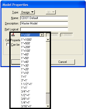
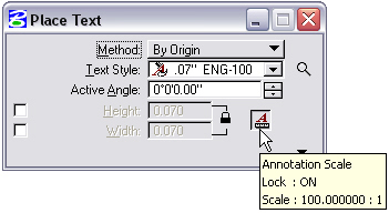
The Annotation Scale lock is on by default in the CDOT Workspace. All text and dimension text is scaled according to the Annotation Scale selected in the Model Properties. The default annotation scale model property is 1"=100'. To place text for other plotted scale factors, change the text size by setting the annotation scale model properties.
From the MicroStation pull-down menu, select File > Models (or click the Models icon on the Primary Tools toolbar). Then select Edit Model Properties to access the available scale as shown in the following figures:


Note: To enable scaling of text, make sure that the Annotation Scale
Lock is turned on in the Place Text command before placing
your text.

This link will show the CDOT color table. The CDOT_color.tbl is attached by default to all CDOT Seed files. The colors within the table correspond to the color symbology specified in the level libraries. Colors are specified to ensure consistency and to enable users to easily identify data. Colors are assigned a number that MicroStation reads to determine the correct color to display.
To verify that the correct color table is being used, select Settings > Color Table. If the colors are not representative of the CDOT Color table, select File > Default and then select Attach. This will ensure the correct color table is being used.
A line weight in MicroStation is defined by a numerical index within the range of 0-31 designating the thickness of the line used when plotting a graphic element. CDOT uses line weights 0-7 in the workspace. These weights correspond to “ByLevel” weight assignments within the Specialty Groups Level Libraries.
The following links show the custom linestyles that have been developed for use within CDOT. The linestyles are contained within the workspace in a MicroStation Resource file called CDOT-Topo.rsc. These linestyles correspond to “ByLevel” linestyle assignments within the Specialty Groups Level Libraries.
CDOT's Line Styles - Page 1 of 2
CDOT's Line Styles - Page 2 of 2
The patterns below are available in the CDOT workspace from the pattern.cel cell library. These cells have been created to look correct on a 1"=100' drawing. Scale the patterns as needed in the patterning dialog box to accommodate different scale drawings.


BearingPad Bronze


Concrete Dot


Earth Embankment


Gravel Herringbone


Honeycomb Masonry


Riprap Rock


Sand Steel


Timber 1 Timber 2


Timber 3 Timber 4

Wetland